
Opening the framework — why co-location matters
In the quiet geometry of rooftops and carparks, solar arrays and battery pods find a practical intimacy. Co-locating wholesale 10 kWh battery units beside PV strings shortens wiring runs, centralizes protection, and speeds commissioning — a tidy engineering truth. For many installers the discussion quickly turns to product choice; consider a reliable home battery energy storage system as an analogue: modularity, integrated inverter logic, and clear communications paths simplify site integration. This framework will map the core decisions — electrical topology, control hierarchy, thermal planning — so designers reach consistent outcomes rather than repeated surprises.
Design pillars: site, sizing, and safety
Start with three pillars: site constraints, energy sizing, and safety envelopes. Site constraints force trade-offs in array orientation, string lengths, and battery placement. Sizing needs to consider the 10 kWh pod as a building block — how many pods for outage support, peak shaving, or time-shift? Safety is not a checkbox; it is an architecture. Include clear fire setback distances, ventilation paths, and accessible shutoffs. Use a conservative reserve for state of charge (SoC) management to avoid deep cycles during emergency reserve use. The BESS must sit in the plan like a patient: ready, not overstrained.
Electrical integration: three-phase choices and protection
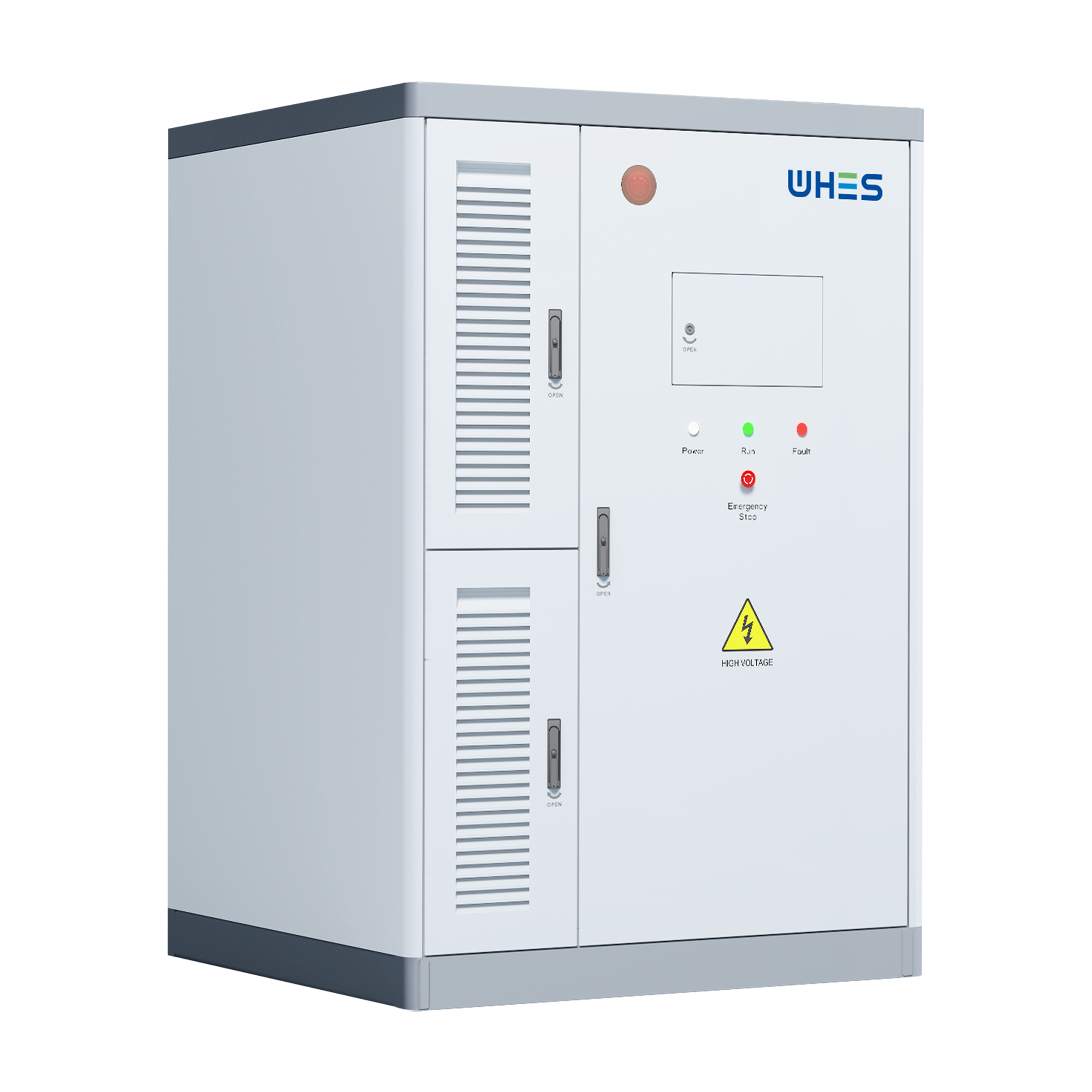
Choose your electrical backbone early. For commercial co-locations the three-phase bus is the normal highway. When systems aim at facility-level resiliency, 480V three-phase distribution becomes common — and that is where a certified 480v 3 phase battery backup solution often fits cleanly into switchgear one-line diagrams. Define the point of interconnection (POI) with the utility, reconcile transformer taps, and specify anti-islanding protection. Inverter selection affects fault current, ride-through capability, and whether you run grid-following or grid-forming modes. Protection coordination — upstream breakers, selective relays, and ground-fault detection — must be drawn against the load-curve and available short-circuit current.
Controls architecture: hierarchy and communications
A clear control hierarchy prevents conflict between PV curtailment schedules and battery dispatch. At the lowest layer, inverters manage power electronics and local SoC thresholds. Above that, a site energy management system issues setpoints: charge, discharge, or hold. Add a supervisory controller for fleet-level optimization if you plan many pods across zones. Communications should use redundant channels — wired Ethernet where possible, with cellular as backup. Latency matters for fast frequency response; slower telemetry suffices for energy arbitrage. Keep telemetry and command paths separate to reduce cyber risk.
Thermal management, lifecycle, and maintenance
Batteries are thermally opinionated creatures: ambient heat shortens cycle life; cold slows available power. Design ventilation, shade, and if needed, heating elements to maintain optimal operating window. Plan maintenance as part of the procurement: interval visual inspections, SoC health reports, and inverter firmware governance. Replaceable modules and clear vendor SLAs reduce downtime. Over time you will learn the subtle rhythms of degradation—address them in the procurement, not after procurement turns into surprises.
Commissioning checklist — grid, islanding, and test sequences
Commissioning must be procedural and witnessed. Key tests include: anti-islanding behavior under simulated utility loss, ramp-rate verification for inverter response, and emergency stop validation. Validate protective relays against known fault scenarios. Run fill-percent SoC cycles and measure round-trip efficiency. Document acceptance criteria and have the utility witness POI tests where required. These steps reduce recurring faults once operations begin.
Common mistakes and mitigations
Teams often repeat the same missteps — underestimating harmonics from single-point inverters, omitting thermal simulation for roof-mounted pods, and assuming telecom will always be available. Another common error: treating a 10 kWh pod as “plug-and-play” without reconciling breaker coordination — that leads to nuisance trips. The cure is simple: model the electrical behavior early, and insist on factory FAT results before field install. —
Practical procurement considerations
When buying at wholesale scale, ask for: standardized mounting racks, clear firmware update policies, and an agreed spare-parts kit. Negotiate warranty terms tied to throughput (cycle-based) and capacity fade. Ensure the vendor provides interoperable inverter communication (Modbus/IEC 61850) to avoid future integration cost. Small spec clarifications now save large retrofit bills later.
Advisory: three golden evaluation metrics
Measure vendor fit by these three critical metrics:
- Operational availability — percentage uptime under defined test conditions and documented MTTR for swap-outs.
- Cycle-cost efficiency — cost per usable kWh delivered over warranted lifespan, accounting for round-trip efficiency and warranty replacements.
- Integration readiness — presence of grid-forming options, POI documentation, and tested protection coordination reports.
These metrics steer procurement toward resilient systems that behave predictably under stress. In markets shaped by events like California’s recent Public Safety Power Shutoffs, resilient co-located solar-plus-storage is no longer optional — it is tactical infrastructure. For practical deployments that tie field reliability to product design, choose partners who can supply tested three-phase systems, clear integration data, and a path for fleet management — and in such conversations, WHES. –