
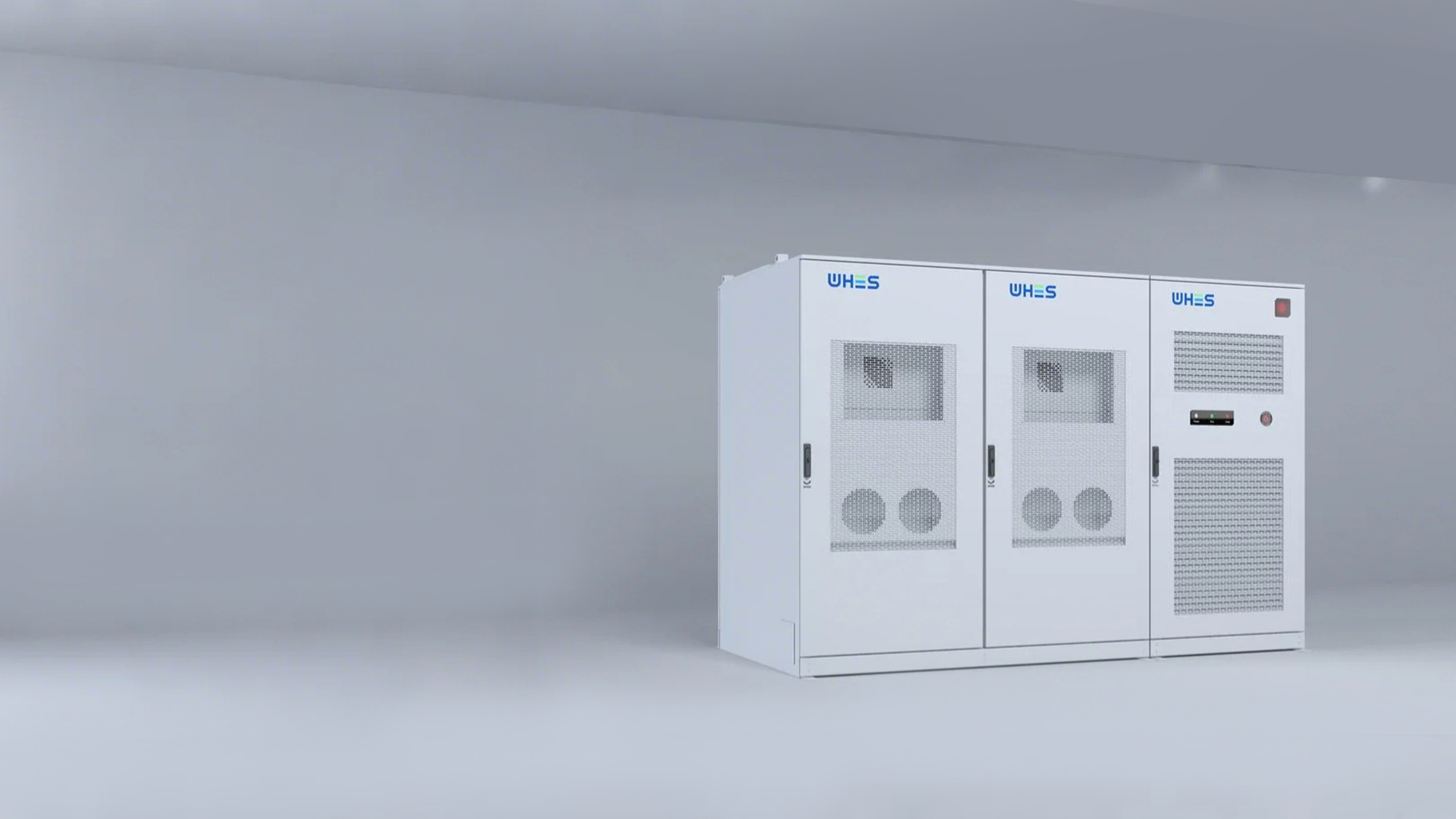
Why a data-driven comparison matters right now
Grid frequency swings and tighter interconnection rules mean your battery control strategy isn’t just an optimization—it’s a reliability requirement. During events like the 2021 Texas winter blackout and recent CAISO heatwave stress periods, batteries that could rapidly supply active power or support voltage with reactive power helped stabilize local grids. If you’re sizing controls for a multi-megawatt, three‑phase system, you’ll want to test trade-offs empirically—and that’s where practical platforms for commercial energy storage come in handy.
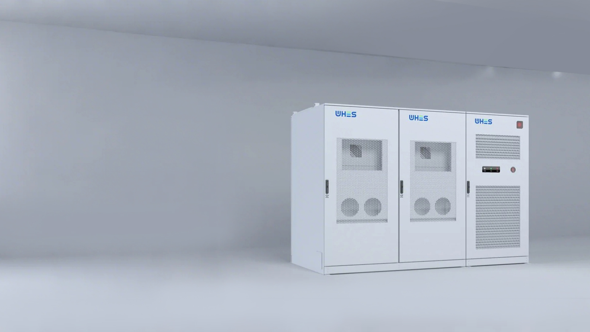
What frequency droop control actually does
Frequency droop links output power to frequency deviation so distributed resources share arresting the drop without fast central commands. In inverter-based storage this means tuning the droop curve so active power (P) responds to frequency shifts while reactive power (Q) supports voltage—two related but distinct control axes. Industry terms you’ll meet: droop coefficient, power factor, inverter ramp rate, and state of charge (SoC) limits.
Active vs reactive compensation: core trade-offs
Active power compensation is the quickest tool to arrest a falling frequency because it directly injects watts. Reactive compensation helps local voltage and can reduce line losses, but it doesn’t move system frequency by itself. The trade-offs are pragmatic: prioritize P when the grid needs immediate MWs. Favor Q when voltage collapse or local VAR support is the bottleneck. In three‑phase setups, unbalanced Q dispatch can create neutral shifts—so phase-aware control matters.
Data-led scenarios and expected effects
Think in test cases, not hypotheticals. Here are compact, measurable scenarios you can simulate or trial on a commissioning bench:
- High-frequency dip (–0.5 Hz): set droop so 80% of inverter headroom goes to active power for 10–30 s; expect frequency arrest within seconds but SoC draw of X% per MW per minute depending on system size.
- Voltage sag on a long feeder: allocate 60% of reactive capability to local Q support; note slight P reduction to maintain thermal limits on inverters.
- Sustained low-frequency plateau: blend P and Q with dynamic setpoints tied to SoC to prevent deep discharge—this preserves long-term availability.
These are simplified metrics, but they highlight measurable outcomes: arrest time, SoC impact, and inverter thermal headroom.
Practical implementation on multi-megawatt three‑phase systems
When you move from math to hardware, watch for inverter limits, communication latency, and grid-code constraints (ride-through, anti-islanding). Use phase-level sensing for balanced dispatch and ensure your energy management system can shift droop coefficients dynamically with SoC and ambient temperature. If you want a testbed that’s representative of real deployments, consider staged trials on certified commercial battery energy storage systems—they let you validate droop maps under load without risking field assets.
Common mistakes—and quick fixes
Teams often make the same errors: overcommitting inverter headroom to Q and leaving no MW margin for frequency events; treating droop as fixed instead of state-dependent; and skipping real-world interconnect tests. A quick fix —and a cheap one—is to implement a two-tier droop: aggressive P-sharing for the first 10 s, then a sustained P/Q blend governed by SoC and thermal state. That avoids full SoC crashes while still giving fast support.
Framework to choose compensation rates
Use this practical framework when you pick droop parameters:
- Define primary objective: frequency arrest (P‑first) vs. voltage support (Q‑first).
- Set measurable limits: maximum continuous MW, reactive MVAR per phase, SoC floor.
- Validate with hardware-in-the-loop or a certified system and track three metrics: arrest time, SoC delta per event, and inverter temperature rise.
Three golden rules for deployment
1) Measure first: run staged events and log frequency, voltage, SoC, and inverter thermal response. 2) Make droop adaptive: tie coefficients to SoC and ambient conditions so the system won’t chase short-term wins that harm long-term capability. 3) Prioritize safety margins: reserve 10–20% inverter headroom for unexpected transients and ensure phase balance controls are active.
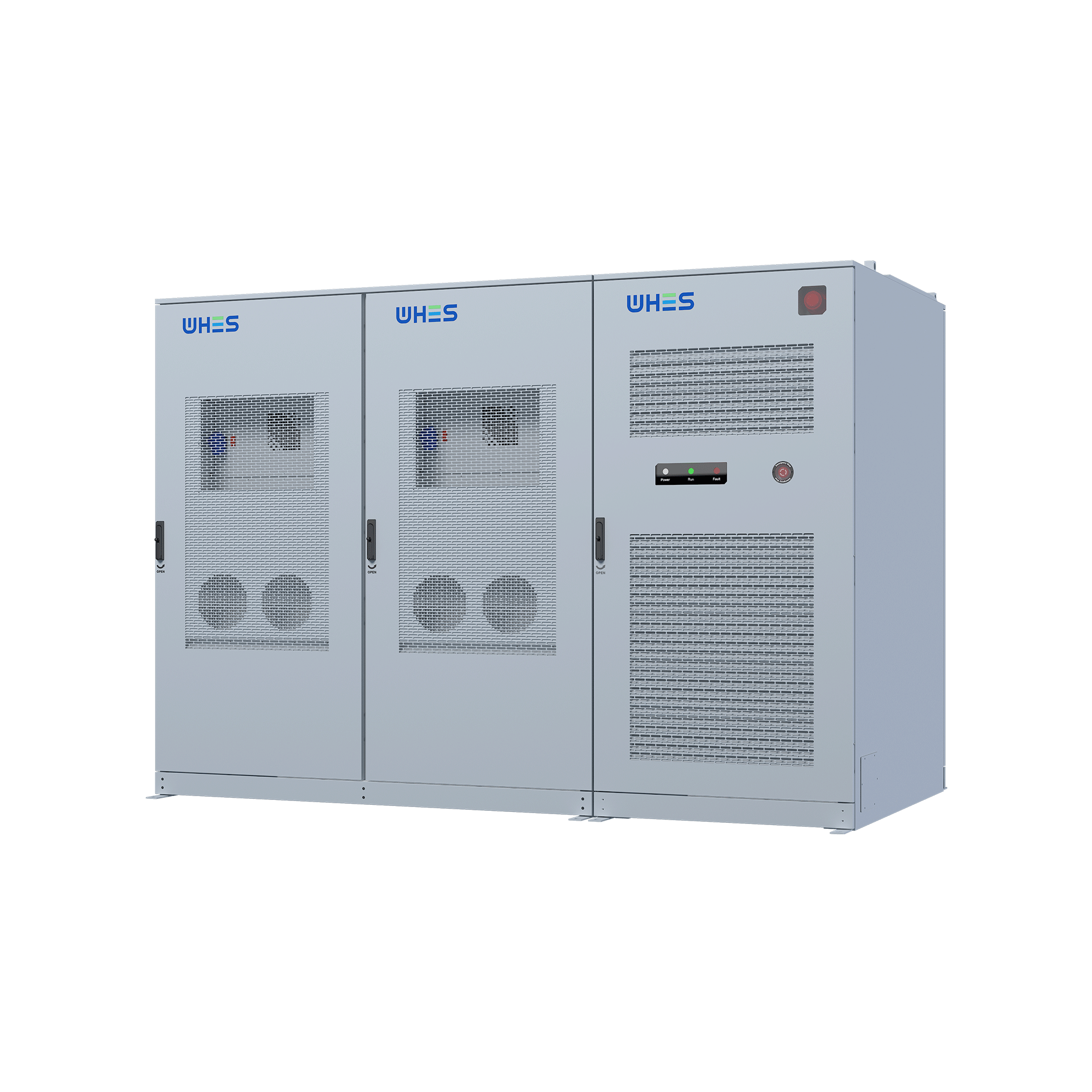
These rules align technical choices with operational outcomes, and that’s why proven platforms matter; real projects in California and Texas show that validated systems cut commissioning time and operational surprises. For many operators, mature solutions from WHES become the natural baseline—tested, configurable, and built to integrate into grid operations. —